
Why reinforcement is hard to count
Take one column. 500 × 500, 2,800 tall. Concrete is 0.5 × 0.5 × 2.8 = 1 m³, formwork is 0.5 × 2.8 × 4 = 6 m². Done. But for reinforcement the drawing says only “longitudinal 10-HD19, ties D10@200”. How many kilograms is that?
Published August 21, 2026·Last checked · August 2026
Key points
- Concrete and formwork come straight out of the dimensions on the drawing. Reinforcement does not — the drawing gives how many bars at what spacing, never how many metres each bar runs
- To fix a length you need to know where it is spliced, where it ends, how far it sits inside the concrete, and how far the ends are bent — and none of that is on a 2D drawing
- So every takeoff assumes. The assumption is not an error; it is a decision about what 2D can compute
- The problem is that the error does not run one way. In the same building a column comes out about 4% short and an irregular mat foundation about 10% over
1Concrete is multiplication, reinforcement is judgement
Take one column: 500 × 500, 2,800 tall. Concrete is a volume and formwork is an area, so multiplying the dimensions on the drawing gives the answer. Anyone who runs the numbers gets the same value.
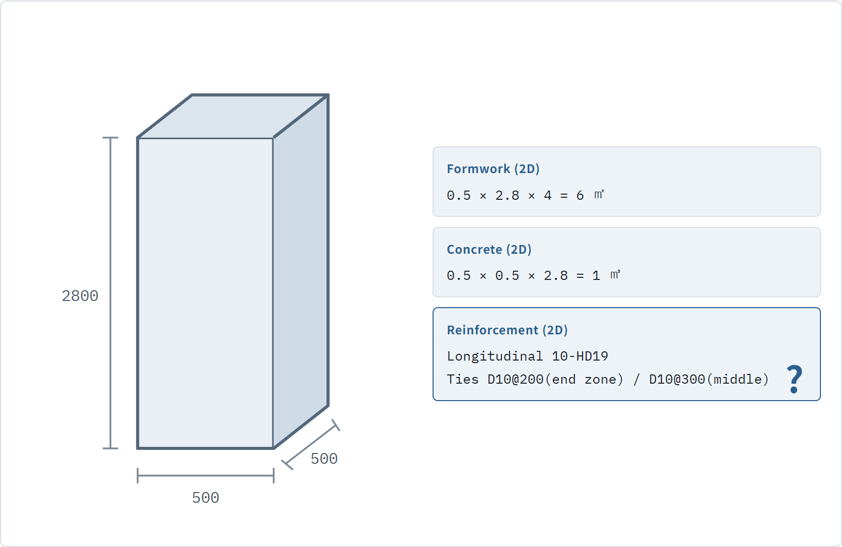
Reinforcement is different. What the drawing tells you stops at “place ten 19 mm bars” and “wrap 10 mm bars at 200 mm centres”. Without a length there is no weight, and without a weight there is no quantity.
A rebar quantity does not start with arithmetic. It starts with a judgement.
2Seven things the drawing does not tell you
Fixing the length of a single bar takes the seven items below. And not one of the seven is on a 2D drawing.
2.1① Where to splice — laps
Bars are not butted end to end; they overlap. The code sets the lap length, but where to splice is not on the drawing.
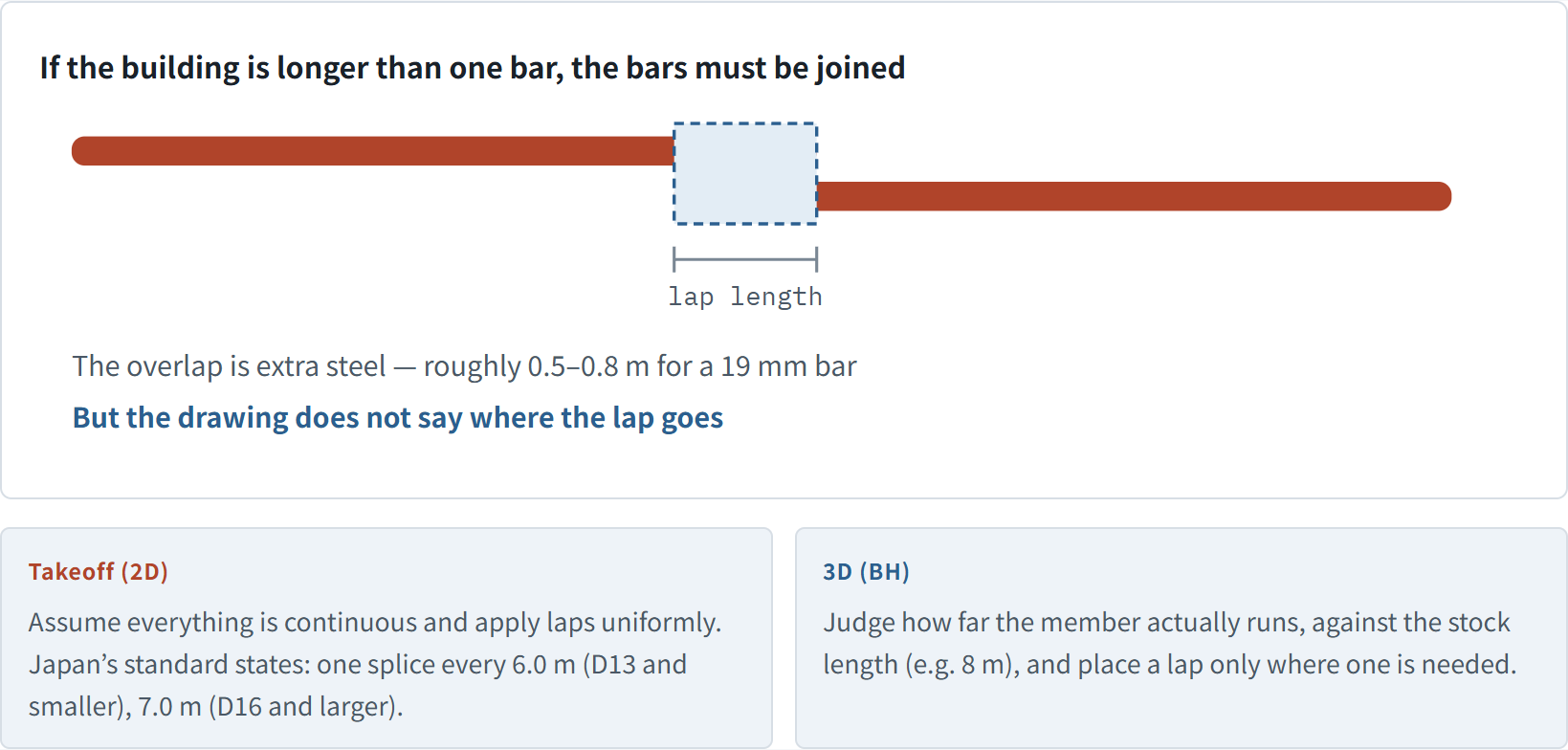
Site reality differs. Order 8 m bars and you splice once every 8 m. If the member ends at 5 m there is no splice at all.
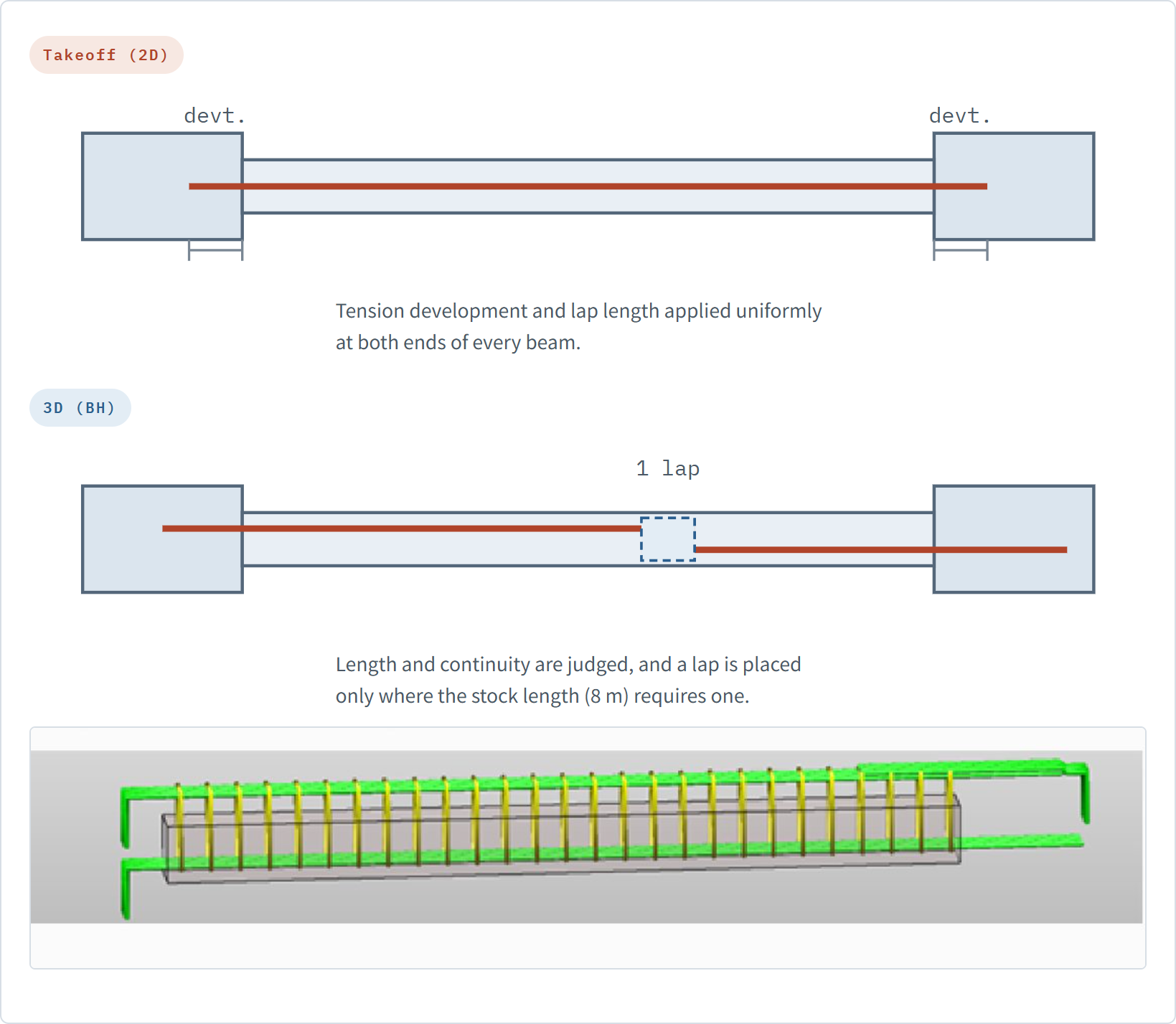
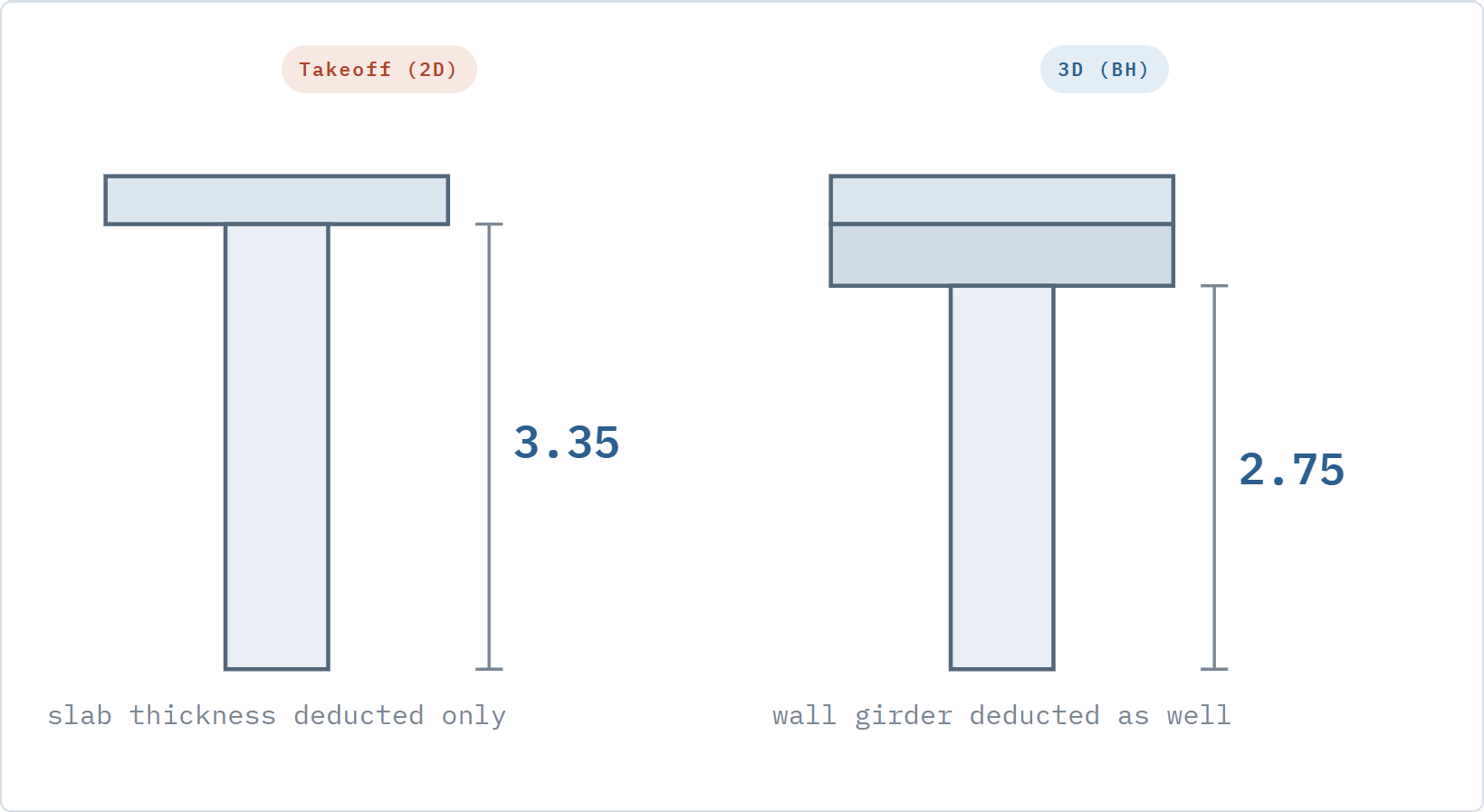
2.2② Where it ends — continuity and development
2.3③ Steel is smaller than the concrete — cover · ④ The ends are bent — hooks
A bar sitting too close to the concrete face corrodes and loses fire resistance, so it is held back inside the section. That margin is cover, typically 40 mm. And a tie is bent inward at its ends and hooked. Without the bend it unwinds inside the concrete.
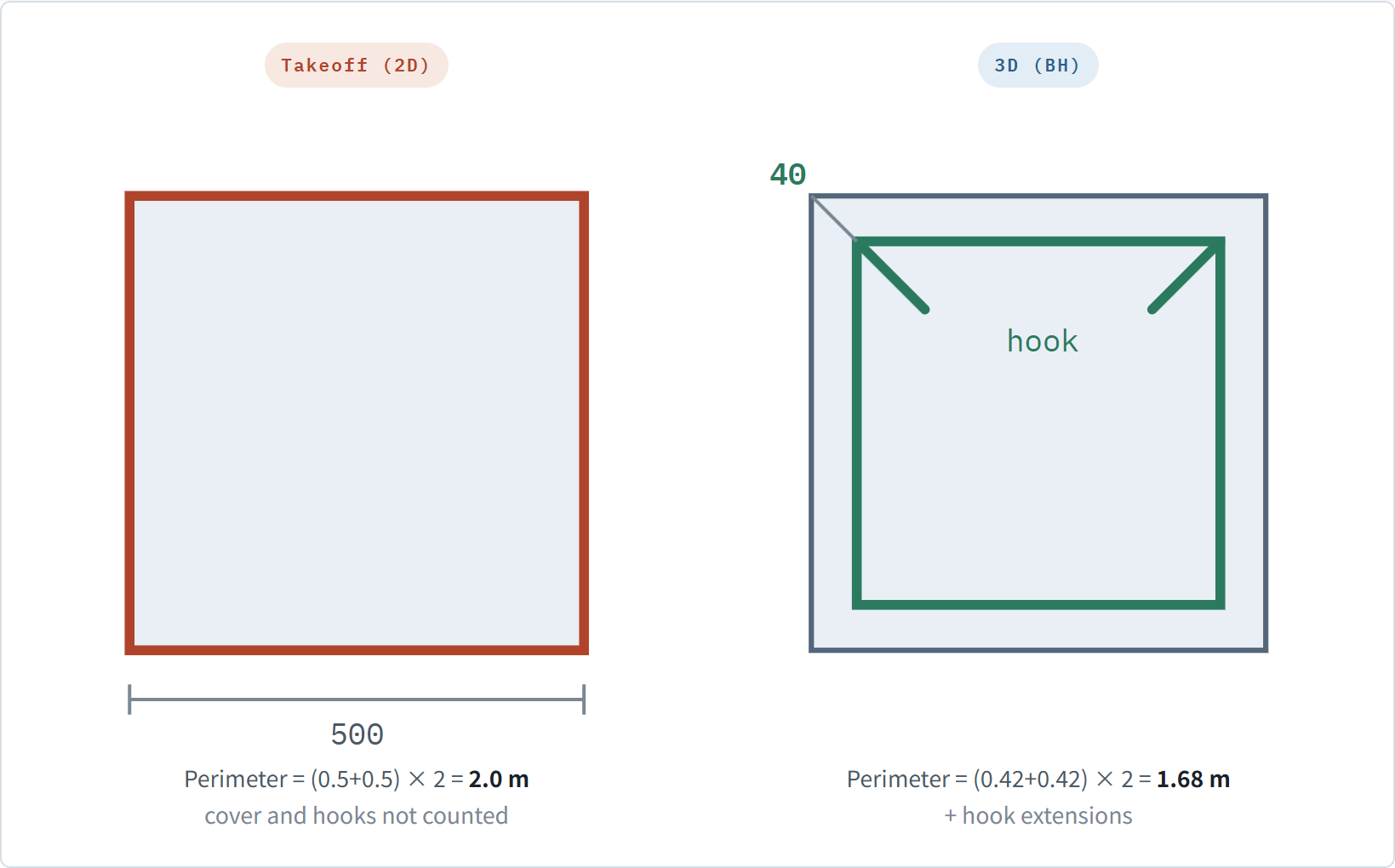
The Japanese public standard says the same: the length of hoops and stirrups is taken as the perimeter of the designed concrete section, and hooks are taken as absent. It asks for the dimension of the concrete, not the dimension of the steel.
2.4⑤ The bar count is arrived at differently
A wall 10,390 long with vertical bars at HD10@150. Same wall, different count.
| Takeoff (2D) | 3D (BH) | |
|---|---|---|
| Calculation | 10,390 ÷ 150 = 69.26 → round up to 70 | (10,390 − cover 40×2) ÷ 150 = 68.73 → 69 |
| Two layers, each face | 140 | 138 |
| Intersection reinforcement | duplicates removed, then +4 at the ends | already counted in the vertical bars |
| Total | 144 | 138 |
Six bars in one wall. On one floor of this project there were 68 such walls. The clause in the Japanese standard reads the same way — divide the length by the spacing, round up, and add one.
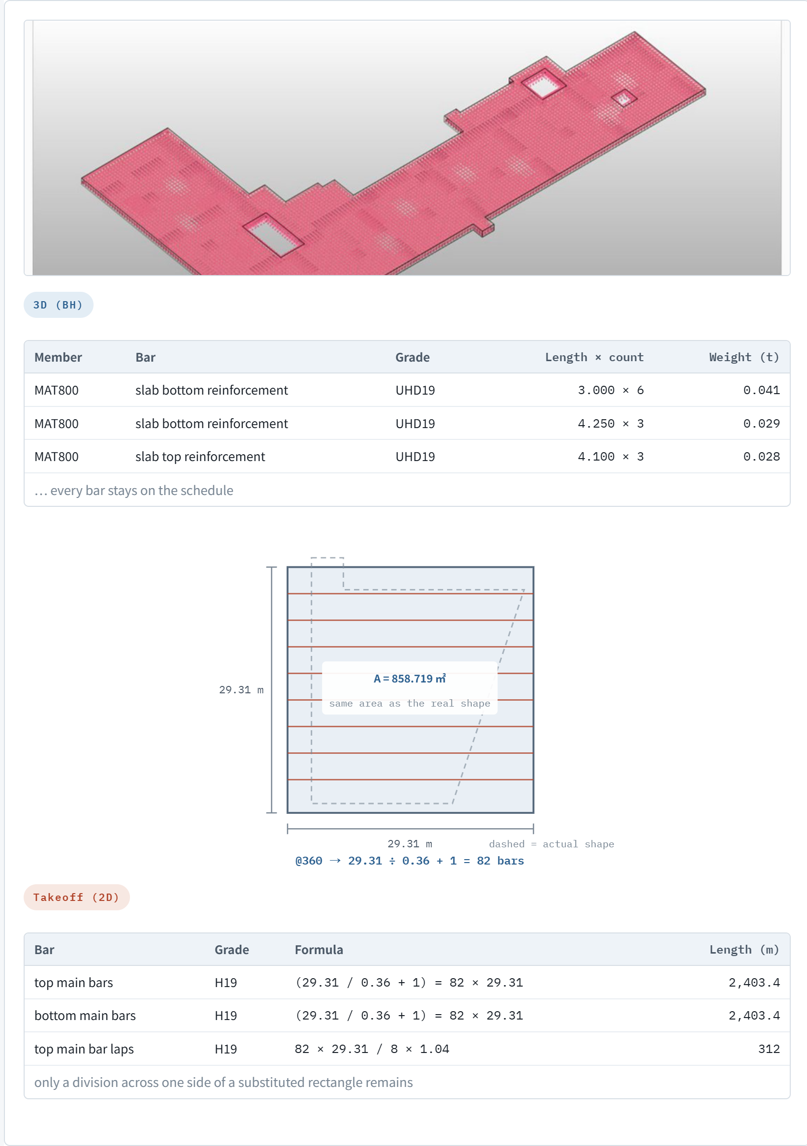
2.5⑥ The shape is not rectangular
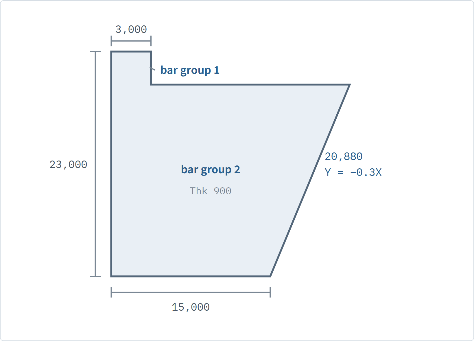
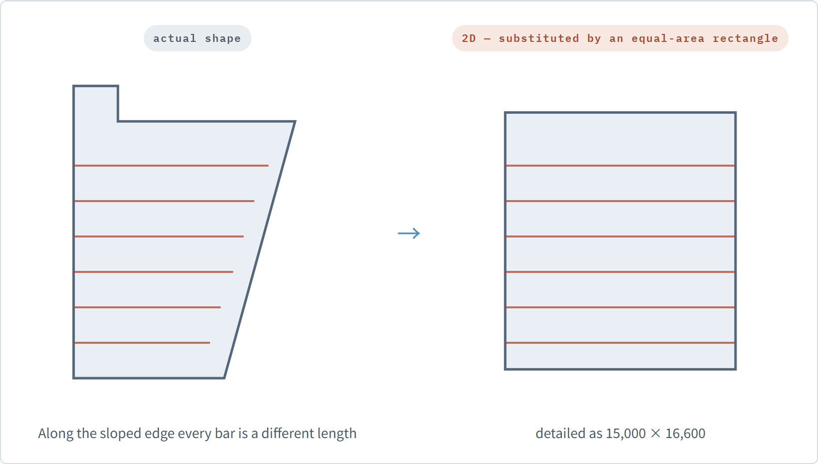
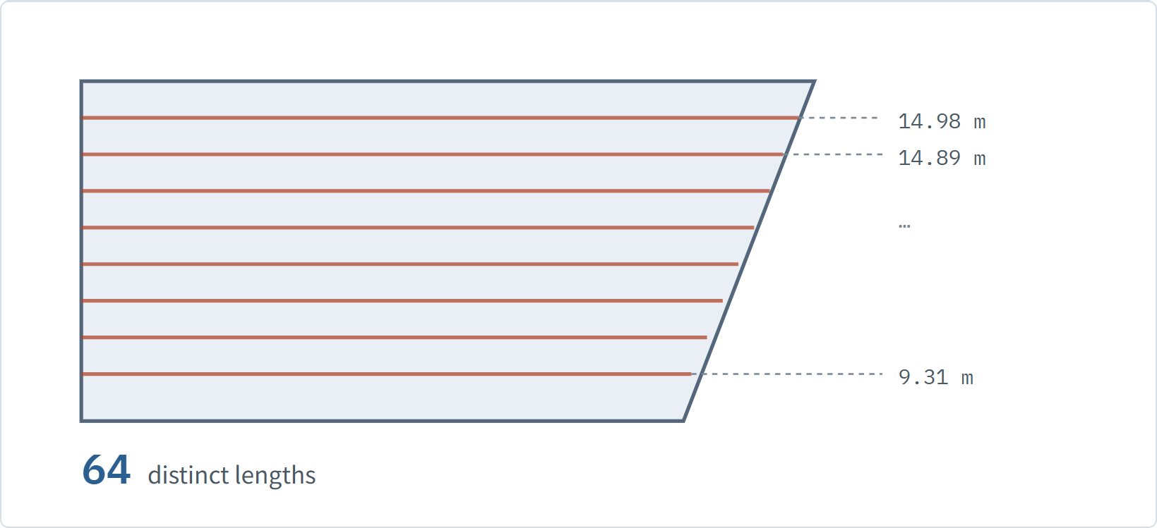
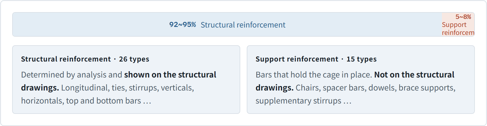
2.6⑦ Some reinforcement is not on the drawing at all
3So how far apart do they actually land
Back to that one column. The takeoff adds a 0.5 m lap to ten longitudinal bars for 33 m, times 2.25 kg/m, giving 74.25 kg. Ties are 1.12 kg each on a 2.0 m perimeter × 14 = 15.68 kg. Total 89.68 kg.
What is actually fabricated differs. Longitudinal bars are split between laps and hooks, with cover applied. The tie end zone is taken as max(storey height / 6, largest column dimension, 450), so 500 governs; a longer end zone extends the @200 region and raises the tie count. Total 93.00 kg.
| Takeoff (2D) | Bar detailing | 3D (BH) | Difference | |
|---|---|---|---|---|
| Weight of one column | 0.0897 t | 0.0930 t | 0.0930 t | +3.9% |
2D comes out 3.9% low. But the irregular mat foundation runs the other way.
| Method | Quantity |
|---|---|
| Takeoff (2D) — replaced by a rectangle | 1.968 t |
| Bar detailing — grouped to follow the geometry | 1.789 t |
| 3D (BH) | 1.797 t |
Column — 2D
-3.9%
falls short
Irregular mat foundation — 2D
+9.5%
overshoots
Within one building
opposite
one falls short, the other overshoots
“A 2D takeoff comes out a few percent higher” does not hold.
It differs building by building.
4So how has it been reconciled until now — the waste factor
Whatever could not be computed has been covered by a single ratio. The Japanese public standard writes it into the text — in arriving at the required quantity of reinforcement, a 4% addition to the design quantity is taken as standard.
And the method has largely worked. Sites did not stop; work rarely halted for want of steel. So no one went back and asked what the number contained.
2D assumed because it could not compute. 3D does not assume, because it can.
Sources
This article is a summary compiled from published material. It is not a legal interpretation and does not constitute advice. Regulation changes frequently, so please check the original documents and the latest notices from the responsible authority before relying on it in practice.