
Where do you start with rebar BIM?
Every company gets as far as “we will adopt BIM.” The next decision never comes. Which building, which scope, what has to be agreed before anything is modelled — all of it stays blank. This article sets out that first step in four stages.
Published August 18, 2026·Last checked · August 2026
Key points
- The real blocker is not a lack of tools but knowledge split across two people. Those who know rebar detailing mostly work in 2D; those fluent in 3D barely know detailing
- Pre-construction review is customary in Japan for a reason: seismic design → thicker bars → congestion → nothing can be changed on site. So the work moves forward into design
- Start not with the whole building but with the zones a 2D review effectively cannot cover: skewed intersections, base isolation footings, multi-directional joints, congested zones
- Before any model, agree five operating rules. One reading of a development-length rule, one choice of splice method, and the tonnage moves
1The problem is not the tool. It is that the knowledge is split
Ask a company why it has not started with rebar BIM and the answer is usually about tools. The software is expensive, nobody can operate it, it is unclear which product to buy.
What we keep finding in the Japanese market is different. The people who know rebar detailing mostly work only in 2D, and the people fluent in 3D barely know detailing. Rebar judgement and three-dimensional handling never meet inside one person.
There was no environment where the two could be put side by side and examined from every angle. The tools existed. The knowledge sat in two separate places.
So the answer here is not “model everything.” You start in four stages. Each stage is complete in itself, and whether you go on to the next one is decided by what the previous one produced.
2Why Japan reviews before construction
That rebar clash review is customary in Japan gets mentioned often. The reason behind it rarely does. The causal chain is simple.
- Seismic design calls for larger bar diameters and more steel.
- Thicker bars are harder to bend, so there is less room to adjust by hand on site.
- Denser cages leave no room to bend into — at the joint, bars compete for the same space.
- Nothing can be changed during construction. The only remaining option is to adjust during design.
Start without a prior review and rework repeats, with the cost and the time falling mostly on the site. The custom is not culture. It is the residue of losses already taken.
It is not something you can change during construction. So it is pulled forward into design.
That pulling forward is called front loading: problems that would surface during construction are handled in design. All four stages below are simply how that is carried out. Traditionally, “how is this actually going to be built?” was settled only where the design office and the contractor's design department met just before construction began. Front loading moves that conversation inside the design phase.
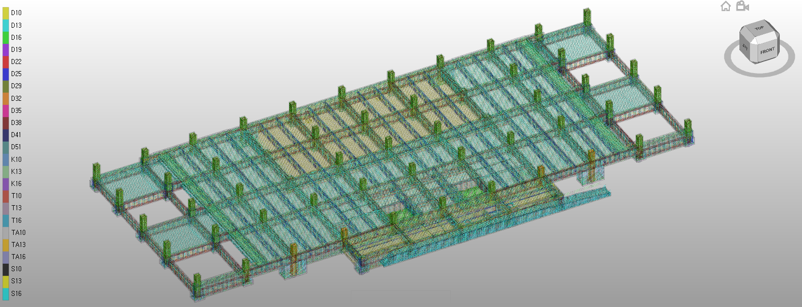
3STEP 01 — Not the whole building. The difficult zones
Companies that cannot decide the first step share one habit: they scope it as the entire building. At that size neither cost nor duration can be judged. Narrow the starting scope to one thing — the zones a 2D drawing review effectively cannot cover.
| Criterion | Why it is hard |
|---|---|
| Columns and beams meeting at a skew | Section drawings assume orthogonal framing, so the real clash location never appears on them |
| Base isolation footings | Anchor plates, anchors and main bars overlap in a short zone; a member section alone cannot show the clearance |
| Joints where beams arrive from several directions | Top and bottom bars from each direction demand the same elevation |
| Congested zones | Satisfy every rule and there is physically no space left |
The deliverable is a list of target zones. Nothing is modelled at this stage. All that is agreed is where to look.
4STEP 02 — What has to be settled before BIM
Reinforcement is not determined by code alone. Code leaves latitude, and company and site practice fill it. Model before that practice is agreed and someone will look at the resulting quantities and say “that is not how we do it.”
| Item to agree | What it settles |
|---|---|
| Cover | Which face the design cover is measured from |
| Long-length bars | How far beyond stock lengths is acceptable |
| Allowance length | How much slack is carried for fabrication and assembly |
| Splice method | Lap, mechanical or welded — and where each applies |
| Priority among development rules | Which rule wins when more than one reading is defensible |
5STEP 03 — The rebar BIM process
This is the process itself. A contractor or a design office can build it in-house, or hand it to us. Either way the sequence is the same. With no 3D staff in place yet, starting with the work outsourced and moving it in-house at STEP 04 is a route too.
There are two entry points. If structural design data (SS7) exists, we read it directly — the shortest route, and the usual one for structural design offices. Contractors and BIM service firms who never receive the design source start from 2D drawing (DWG) recognition.
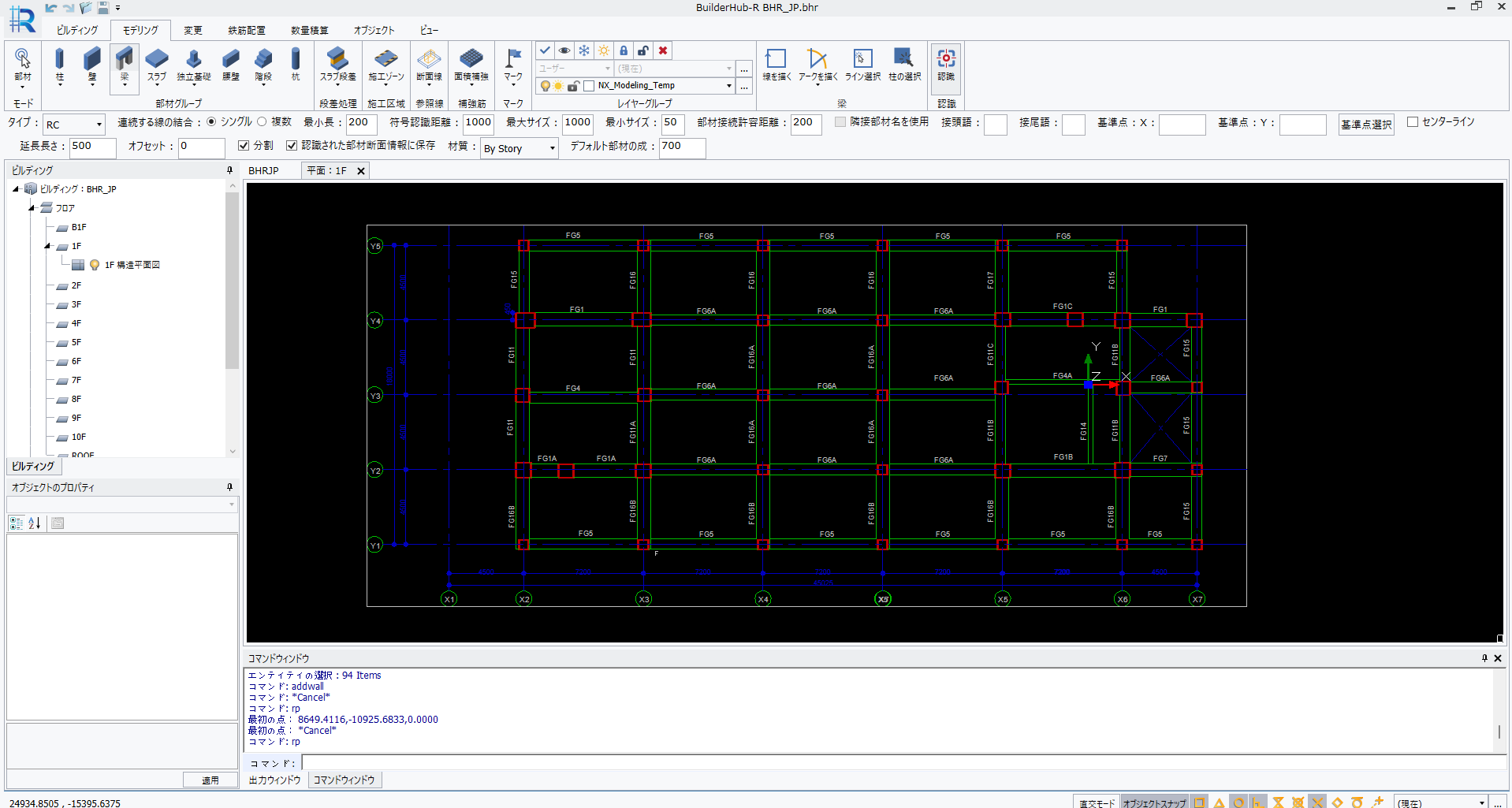
Before recognition
The original structural framing plan, loaded as is
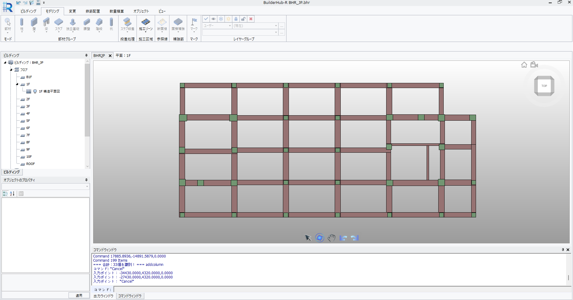
After recognition
Columns, beams and slabs recognised as members, frame generated
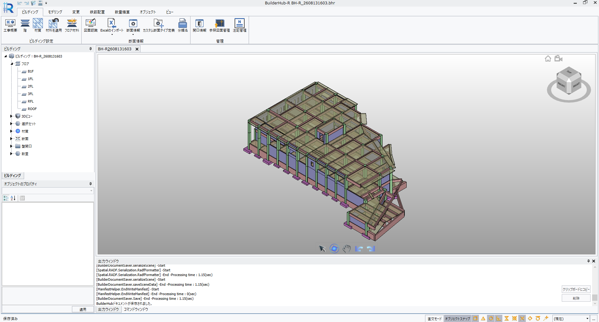
Once the frame stands, the 3D reinforcement model is generated automatically — development, cover, splice positions and bend radii all to real-world dimensions. Joints, exposed column bases, sloped slabs and stairs, the parts that used to take the most hand work, are included. Modelling that took days shrinks substantially.
Next comes automatic clash detection and correction. Clashes come out as a list, and the 3D view shows the overlap in millimetres. You move the bar by that amount, or change its length or angle, and re-check in the same screen.
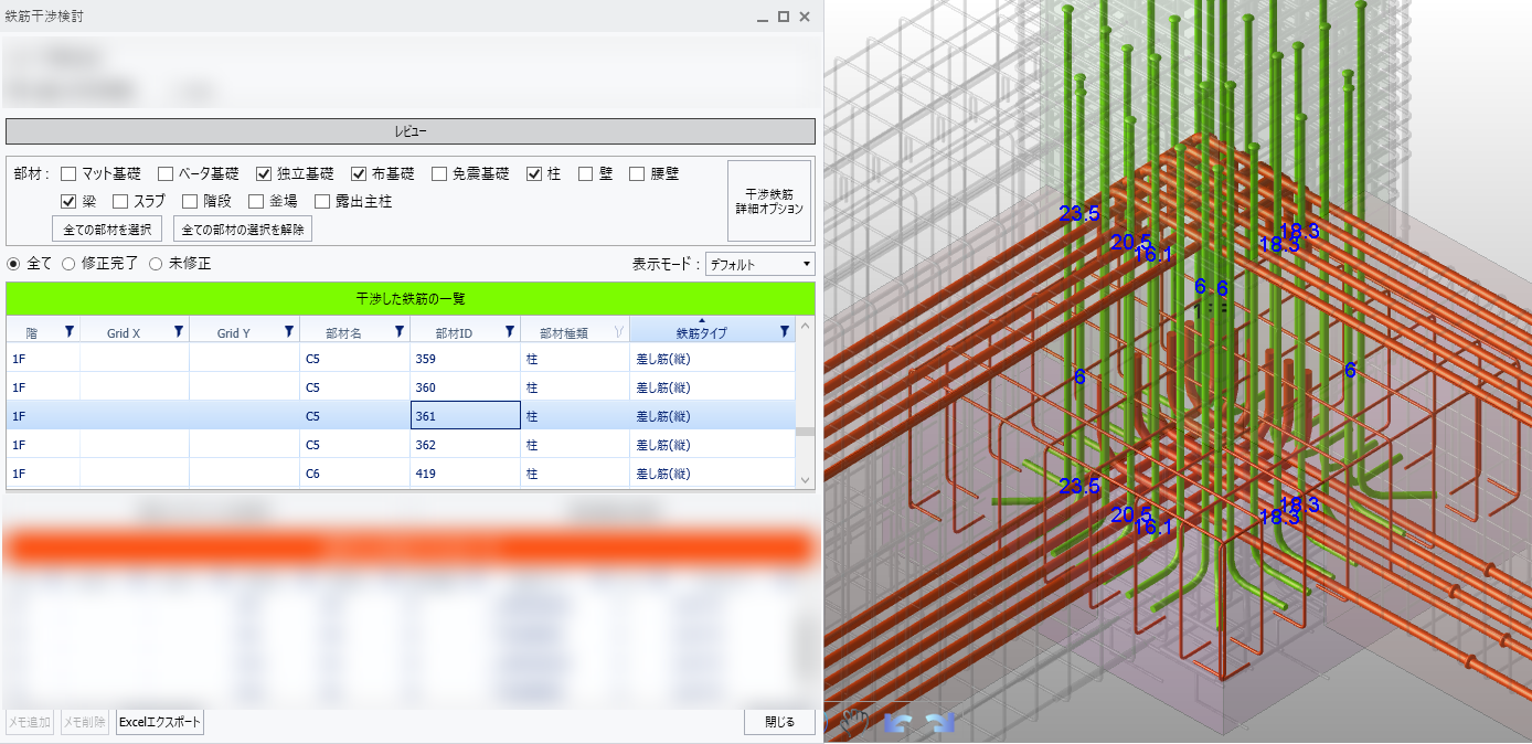
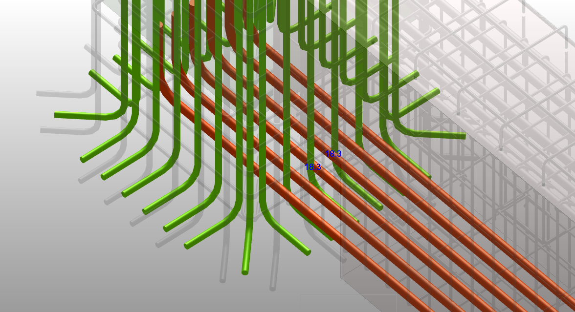
Before
The overlap between beam and column main bars, labelled
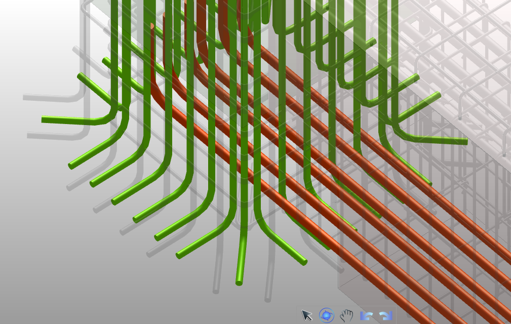
After
Moved by the labelled amount; the clash is gone
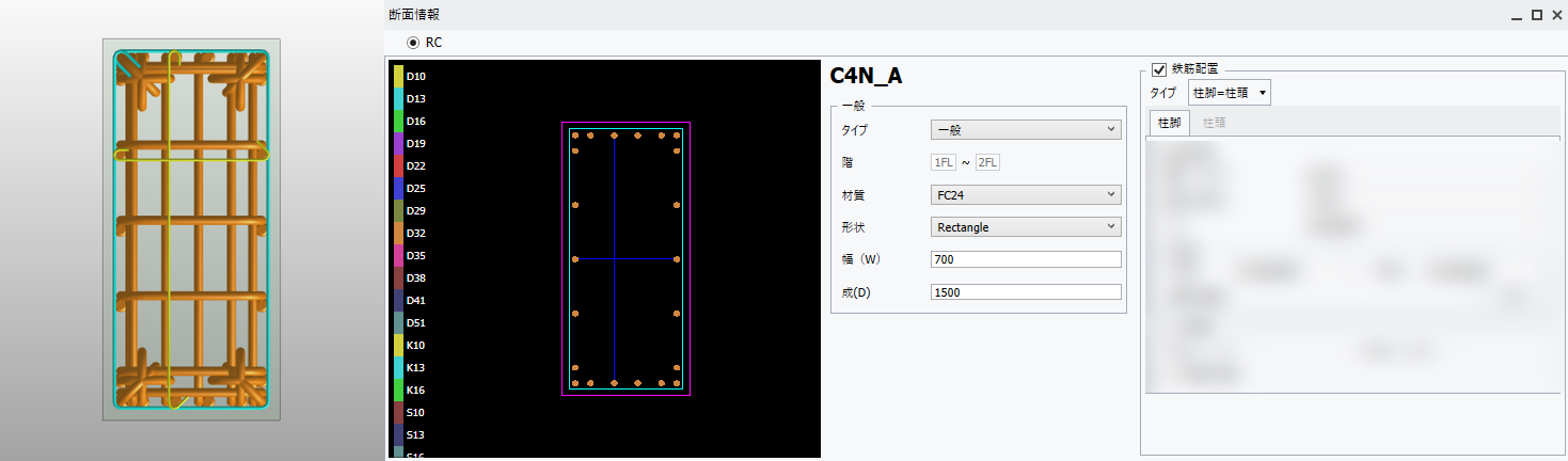
Last is change propagation. When clear spacing or development length falls short and a member size or bar arrangement has to change, editing the value re-reinforces that zone immediately. Adjusting during design is only realistic when changes are not frightening.
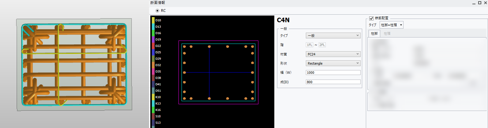
Before change
Section dimensions and reinforcement conditions are entered here
After change
Change the value and the zone is re-reinforced at once
6STEP 04 — Bringing it in-house
Once the rules and the results have settled, the work moves inside. What moves is not the tool but the rules agreed in STEP 02. They can only move because they were written down — and from then on rebar judgement accumulates as the company's own data.
Keeping that order matters. Bring the tool in-house before the rules are settled and deciding the values lands on one person again — which is the problem you started with.
7Three things STEP 03 leaves behind
Run STEP 03 once and three things remain in hand.
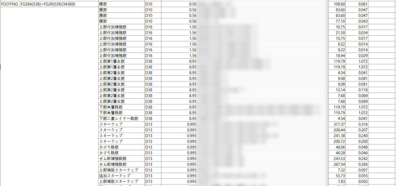
- A clash-resolved model — reinforcement carrying the record of what clashed where and how it was resolved, plus the review report.
- A traceable quantity take-off — not a total figure but the formula behind it: which member, which bar.
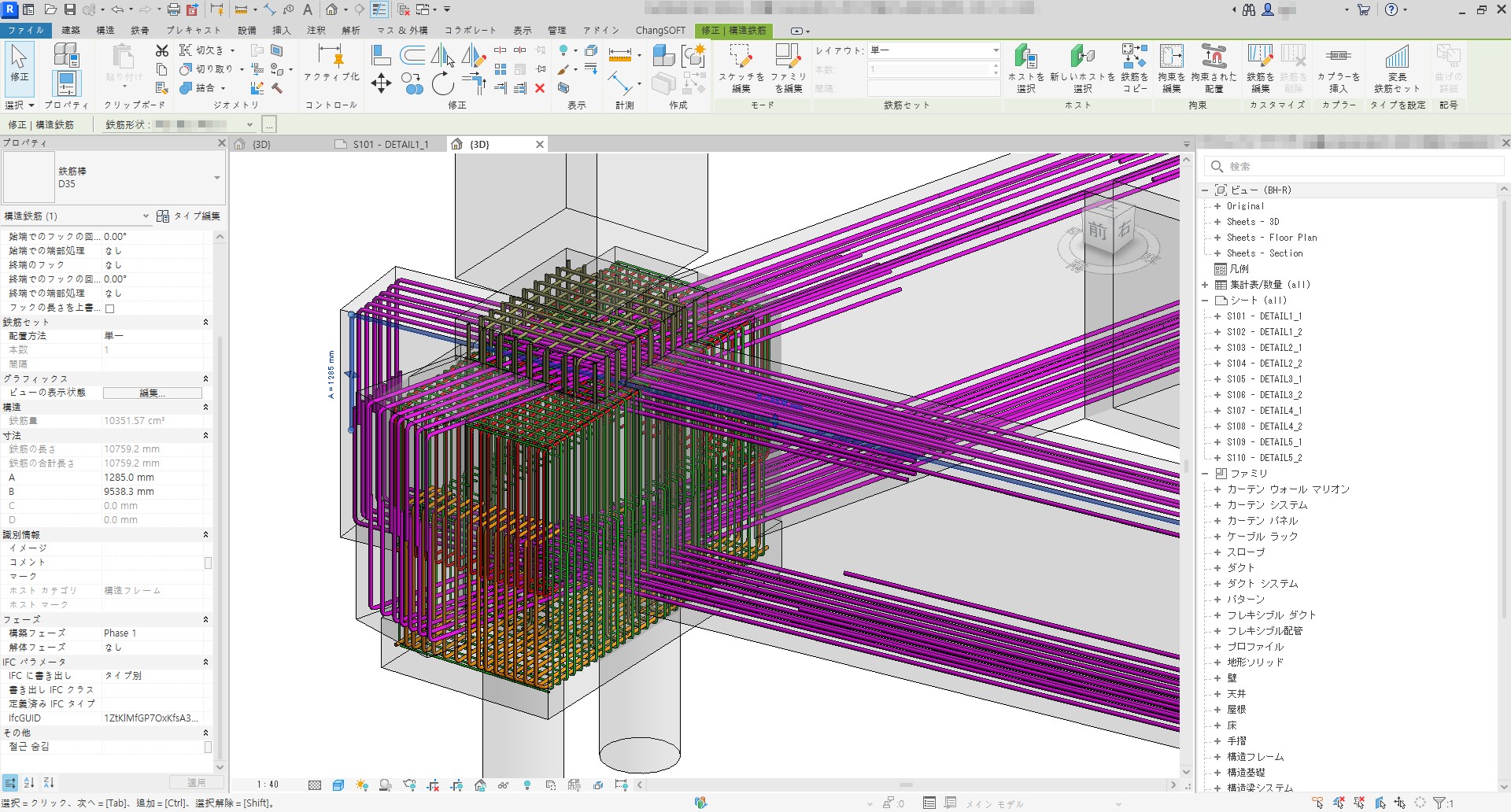
- A Revit model — not a copy of the geometry, but Revit objects where each bar carries its reinforcement data.
8How it has actually been used
Two engagements, anonymised at the clients' request.
| What the client was dealing with | What we did | |
|---|---|---|
| Company A (general contractor) | Already doing rebar modelling, clash review and drawing production in-house with Revit, but it took a long time to complete and was hard to bring to a standard usable as-is on site | We modelled the joint where base isolation footings, spread footings and below-grade elements combine, then took it through Revit conversion and drawing production — delivered within two weeks on this engagement |
| Company B (general contractor) | A wide gap between public-standard estimated quantities and quantities actually placed | Modelled the reinforcement in 3D as actually detailed, took off the quantities, and compared them against the existing figures, separating the differences by cause |
9Why now — and what we still cannot do
Contractors used to re-check drawings that were not fully resolved. As economic and schedule margins have disappeared, responsibility increasingly lands on the design side as well. That gives design offices a reason to start now, and it connects directly to the agreements in section 4.
Plainly, there are things we cannot do yet.
- Native drawing production is on the roadmap — for now drawings are produced via Revit conversion.
- Direct IFC export is on the roadmap too
- Reinforcement rules are implemented to JIS.
You do not have to model everything. One zone that 2D could never show you is enough to start.
Sources
- BuilderHub-R product overviewChangSoft Global
- Both drawings are correct — clash review before constructionChangSoft Global
- So can you adopt it now? — AI rebar seriesChangSoft Global
This article is a summary compiled from published material. It is not a legal interpretation and does not constitute advice. Regulation changes frequently, so please check the original documents and the latest notices from the responsible authority before relying on it in practice.