
The geometry moved to BIM. The rebar check stayed on paper.
On a column base manufacturer's document list, two items sit side by side: BIM data for the column base, and a rebar-study line drawing. The shape went 3D. Checking how that shape meets the rebar did not.
Published August 4, 2026·Last checked · August 2026
Key points
- Manufacturer documentation splits the problem: geometry as BIM data, rebar study as a 2D drawing
- Model a shape as tangled as an exposed column base for real and the clash check moves from 2D to 3D
- BuilderHub-R has the column base product data built in — pick a designation and start modelling, with nothing else to enter
1What the manufacturer's own document list shows
Line up what a column base manufacturer publishes and you can see it plainly. An installation manual, certificates, standard details, column base drawings. And BIM data for the column base. On the same list, there is also a rebar-study line drawing — on paper.
The shape went 3D. Checking how that shape meets the rebar did not.
2It fits on the drawing
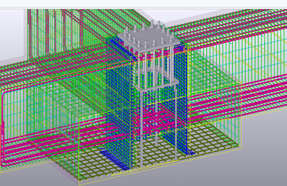
Anchor bolts, anchor frames, the top and bottom bars of the footing, the main bars of the foundation beam, the column ties. On the drawing, that congested volume resolves cleanly. On site, it doesn't — and someone decides on the spot.
Until now, clashes around a column base could only be checked in two dimensions: a section drawing laid over a rebar-study drawing, a handful of cuts standing in for the whole joint. Whatever happens between those cuts, you don't see.
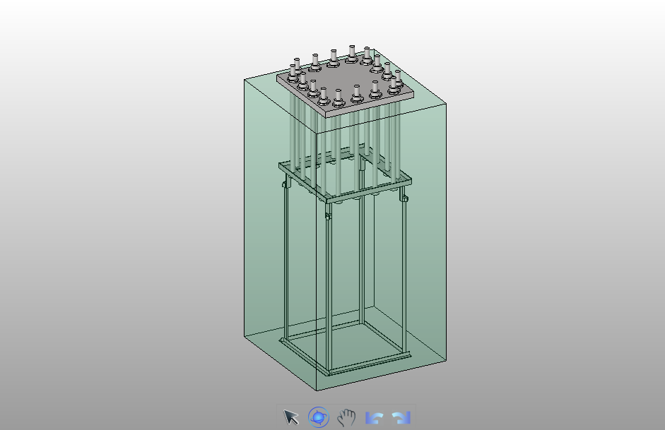
3The catalogue drawing, turned into geometry
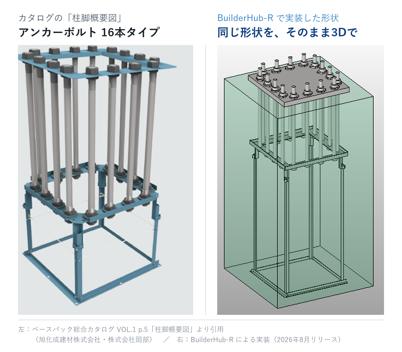
The anchor frame disappears the moment the concrete is poured. It is still the part that decides whether the rebar fits: the height the templates occupy, where the posts stand. Simplify it into a box and you delete exactly the thing the clash check depends on.
4Why the geometry has to be real
Model a shape as tangled as an exposed column base for real, and the clash check itself becomes three-dimensional. Holding it as true geometry rather than a symbol changes five things.
- The check moves from 2D to 3D You look at the whole joint, not at representative cuts.
- A clash reads as “short by this many millimetres” The lower frame and posts of an anchor cage are lines on a study drawing, but in reality they occupy the height the footing bars need to pass through.
- You can answer whether the pedestal bars thread between the anchor bolts — a question that only exists once the bolts have a real diameter and pitch and the ties have a real bend radius.
- Rebar and quantities come from the same model The concrete deduction around the base and the bar lengths stop being two separate inputs.
- The build sequence becomes visible The anchor frame goes up before the rebar, so “the bar won't go in later” is something you find before work starts.
5Pick the designation, and you can start modelling
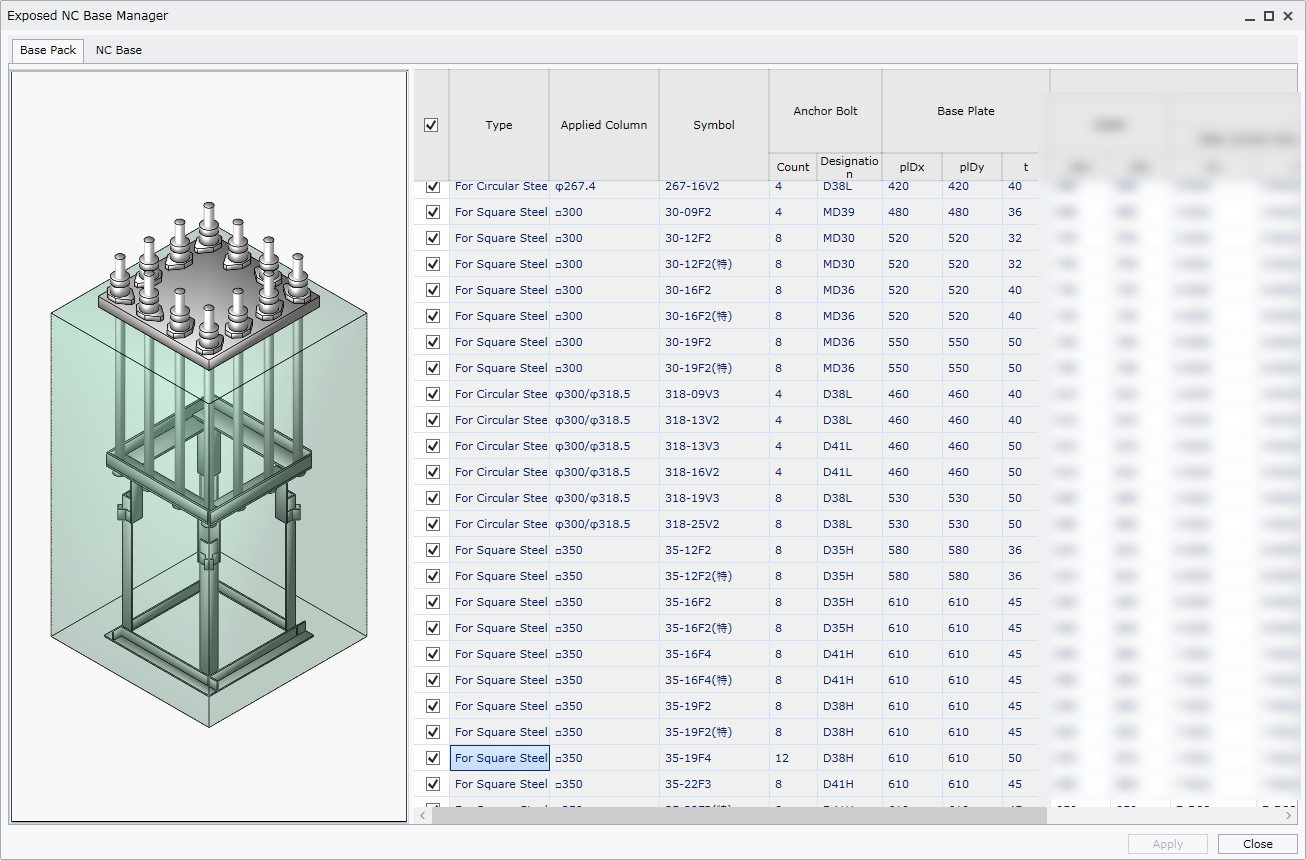
BuilderHub-R ships with the data for the exposed column base products used across Japan built in. Select a product designation and the details — anchor bolt count, base plate thickness — are set for you, so you can start modelling straight away, with nothing else to enter.
The screen does more than show product specifications. The RC pedestal around the base is configured here too. Those are the fields running down the right-hand side; we've withheld how they're composed. What they do is simple enough to say plainly — one product designation settles the rebar conditions for the pedestal as well.
Once the model exists, you can check clashes against the surrounding rebar live, in 3D — cutting review time and catching the problem before anyone breaks ground.
Some of those settings used to mean digging through drawings. The cover below the column base, for one: BuilderHub-R finds the connecting members and computes it automatically. The RC rebar around the base is handled along with it.
And when a clash does turn up, you fix it where you found it. Run the rebar clash check on just the members you selected, then edit anchorage length and type, laps, or the bar nodes themselves until it resolves. Finding and fixing aren't separate places.
What engineers were really deciding was never the placement of a bar. It was the setting: laps, anchorage, cover.
Sources
- ベースパック総合カタログ VOL.1(柱脚概要図・資料一覧)旭化成建材 · 岡部
- NCベースP — 露出型弾性固定柱脚工法日本鋳造
- ハイベースNEO工法センクシア
- スマートベース工法カタログ東京鉄鋼
This article is a summary compiled from published material. It is not a legal interpretation and does not constitute advice. Regulation changes frequently, so please check the original documents and the latest notices from the responsible authority before relying on it in practice.